
Integrated Tools: BIM

DB Manager tools form is a media of communication between the drawing entity data and your enterprise database. This form has two important menu. Drg menu has several tools is to automate, select and modify drawing information locally. DB menu has another set of commands to create, read, update and delete operations of the data between the drawing and your enterprise DB

1. TL2BL Full depth covers from Top LEVEL (TL) to the Bottom LEVEL (BL) 2. SL2BL Net depth covers from Soffit Level(SL) of the Top floor object to the Bottom LEVEL (BL) 3. SLF Defined Depth covers from BELOW the Soffit Level (SL) towards the bottom LEVEL 4. BLF From top of the Bottom LEVEL (BL) towards the Top LEVEL 5. TLF From the Top LEVEL towards the bottom LEVEL - Primary Objects like Slabs/Roofs

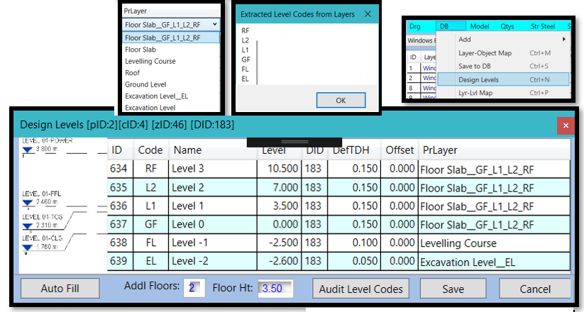
3. The image explains the work flow of PrLayer definition, level and position. Design Level form defines the Floor Slab as PrLayer for top 4 floors – GF, L1, L2 and RF. A level of 10.50 is set for RF LEVEL. When we selected Floor Slab layer in Level Manager (bottom right window) that highlights Floor slab element on the drawing. LT is calculated as 10.50 since its position is 5 TLF, matching top of RF LEVEL. The bottom is LF deduced as LT – DefTDH

A Storey is defined as complete range of objects contained between two FLOOR LEVELs. For example RF to L2 is the Storey. Objects other than Parent = 1 are the objects hosted. For example Columns, Beams and Walls shown in the table are hosted on Floor Slab Object bearing ID = 4

BIM Objects are defined and managed

The form loads all drawing layers into the form grid. Each layer is also mapped to Object list based on string comparison. Manual checks must be carried out to see if the layers are properly mapped to intended objects. Choose grid drop-down and set your set your Object for the layer you wish to change. Click Save when done

Anatomy of DB Mgr: This is the main form that controls the entire DB integration from mapping layers to model generation by several forms
This could be the fastest and smartest way of introducing default levels to your project object layers with fewest drawing data

The relational data between Layers & Objects must also to be mapped to the parent LEVELs. Such mapping is done with help of human-machine interaction as explained in this image

You can verify levels data graphically for each corresponding layer/level accuracy.

Level Manager sets elevations automatically based on Object settings and yet provides changing Level-From(LF) and Level-To (LT) for each element

Tools enable the system to fix the conflicts. Item selections from the grid highlights items on the AutoCAD drawing to help setting easy and accurate levels.
You can verify levels data graphically for each corresponding layer/level accuracy.
 Openings are identified and verified graphically in this feature before moving to level manager |  When loaded first time the oType is set to ‘None’. User is expected to set this manually. Use filters and Ctrl+D to down fill for bulk updating rows. Save the changes. There are 4 types of openings as shown in the image |
|---|
 By looking at the extrusions estimation accuracy is ensured for fitment in to the project implementation with high levels of confidence |  The BOQ Manager has all the saved elements geometrical information in most acceptable BOQ format. Every element references to enterprise level unique BoqID (ID) and FtID referencing Level Manager generated IDs. BOQ shows Object, Layer, Length, Breadth, Depth, PL-L (Polyline/Line Length) and PL-A as Polyline Area and Remarks |
|---|